Gear Shaping Technology: Guide to Machine Operation and Gear Manufacturing
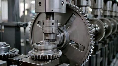
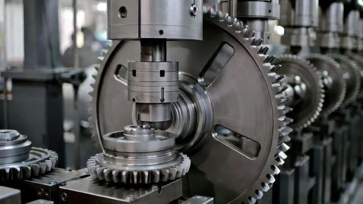
Gear Shaping Technology is a machining method used to produce gear teeth with a specialized cutting tool called a gear shaper cutter. The cutter and the gear blank move in a coordinated manner so that repeated cutting strokes gradually create the required tooth profile.
A gear is a circular mechanical component with teeth around its circumference. When two gears mesh, their teeth transfer rotational motion from one shaft to another. The accuracy of those teeth affects how smoothly the gears rotate, transmit loads, and interact with other components.
Gear shaping is particularly useful for producing external and internal gears. It can also be used for gears that are difficult to manufacture using some other cutting methods.
How a Gear Shaping Machine Works
A gear shaping machine uses a cutter that resembles a small gear. The cutter moves up and down in a reciprocating motion while rotating around its own axis.
At the same time, the gear blank rotates in a synchronized relationship with the cutter. During the cutting strokes, the cutter gradually removes small amounts of material from the blank.
The basic sequence is:
Workpiece preparation: A cylindrical gear blank is prepared to the required dimensions.
Workholding: The blank is securely mounted on the machine.
Cutter installation: A suitable shaping cutter is fitted to the cutter spindle.
Machine setup: Cutter position, workpiece position, speeds, feeds, and other parameters are established.
Reciprocating cutting: The cutter moves through repeated cutting strokes.
Synchronized rotation: Cutter and workpiece rotate in a controlled relationship.
Tooth formation: Material is progressively removed until the required tooth geometry is produced.
Inspection: The finished gear is checked for dimensions, tooth profile, runout, and other required characteristics.
Main Components
A gear shaping machine contains several important mechanical elements.
Cutter spindle holds and rotates the shaping cutter.
Shaper cutter is the cutting tool that generates the gear tooth profile.
Work spindle holds the gear blank and provides controlled rotation.
Work table supports the workpiece and associated holding equipment.
Reciprocating mechanism produces the cutter's repeated cutting strokes.
Feed mechanism controls the relative movement needed to remove material.
Column and machine frame provide structural support for the moving and stationary components.
Control system manages selected machine movements, speeds, feeds, and operating sequences on modern machines.
Importance
Producing Accurate Gear Teeth
Gear teeth must have appropriate geometry so that mating gears can rotate together correctly. Small errors in tooth spacing, profile, alignment, or surface condition can affect gear operation.
Gear Shaping Technology provides a controlled method for generating tooth forms through coordinated cutter and workpiece movement.
Manufacturing Internal Gears
One important application of gear shaping is the production of internal gears, where teeth are formed on the inside circumference of a ring-shaped component.
For example, planetary gear systems contain internal ring gears. Gear shaping can be used for certain internal-gear manufacturing requirements where other cutting arrangements may be difficult to apply.
Producing Different Gear Forms
Gear shaping can be applied to several cylindrical gear configurations. Depending on machine design, tooling, and process parameters, manufacturers can produce spur gears, selected helical gears, internal gears, and other specialized tooth arrangements.
The selected process depends on the required geometry, workpiece dimensions, material, production quantity, and accuracy requirements.
Supporting Gear Manufacturing
Gear shaping is one stage within a larger manufacturing process. A typical gear may go through material preparation, turning, tooth cutting, heat treatment, finishing, cleaning, and inspection.
The sequence varies according to the gear material and its intended operating conditions.
Important Process Factors
| Factor | Meaning | Effect on Production |
|---|---|---|
| Cutter geometry | Shape and dimensions of cutting tool | Determines tooth generation |
| Module | Basic measure related to tooth size | Influences gear dimensions |
| Cutting speed | Relative cutting velocity | Affects machining conditions |
| Feed | Controlled movement during cutting | Influences material removal |
| Stroke rate | Number of cutter strokes | Influences production cycle |
| Workpiece material | Material being machined | Influences tool selection |
| Machine rigidity | Resistance to unwanted movement | Influences accuracy |
| Lubrication | Fluid or method used during machining | Helps manage heat and friction |
Recent Updates
CNC-Controlled Gear Shaping
Modern gear shaping machines can use computer numerical control to coordinate cutter and workpiece movements.
CNC control allows manufacturers to program machining parameters and repeat established sequences. Digital controls can also provide monitoring functions and help integrate gear shaping into automated production lines.
Automated Workpiece Handling
Robotic and automated loading systems can move gear blanks into and out of shaping machines. This can reduce manual handling between machining stages and support continuous production arrangements.
Automated handling can also connect gear shaping with turning, washing, inspection, heat treatment, and other production stages.
Digital Process Monitoring
Modern manufacturing systems increasingly collect information about spindle behavior, machine conditions, tool usage, production cycles, and inspection results.
Connecting this information to manufacturing databases can help engineers analyze production patterns and identify process changes that may require investigation.
Advanced Gear Inspection
Gear inspection has also become increasingly digital. Coordinate measuring machines, specialized gear measurement equipment, optical systems, and software can evaluate tooth geometry and dimensional characteristics.
Inspection data can be compared with design specifications to determine whether the finished gear falls within the required tolerances.
Developments in Gear Standards
International gear standards continue to evolve. ISO 6336-1:2019, which was reviewed and confirmed in 2025, provides fundamental principles and general influence factors for calculating the load capacity of spur and helical gears.
ISO 6336-3:2019, also confirmed in 2025, addresses calculations related to tooth bending strength.
New work is also underway within the ISO 6336 family. In 2026, ISO/AWI 6336-20 entered development to replace the earlier technical specification covering scuffing load calculations.
These developments concern gear design and performance calculations rather than the shaping machine itself, but they are relevant to the wider gear-manufacturing industry.
Indian Gear-Shaping Machine Standards
India maintains a specific standard reference for general-purpose gear shaping machines. BIS lists IS 6679:1972 as the test chart for general-purpose gear shaping machines with table diameters up to 1000 mm. The standard was reviewed in 2023.
BIS also provides a searchable “Know Your Standard” platform where users can locate Indian Standards by standard number or keyword and access associated documents and information.
Laws or Policies
Indian Standards Framework
The Bureau of Indian Standards provides the national standards framework relevant to machinery, gears, transmission components, and manufacturing equipment.
BIS's transmission-devices program covers standards relating to gears, transmission chains, shafts, splines, clutches, couplings, and related mechanical components.
Manufacturers and engineering organizations can use applicable Indian Standards when establishing technical specifications, testing arrangements, and quality-control procedures.
Machinery Requirements
India's machinery regulatory framework can include requirements for particular categories of equipment and components. BIS's Scheme-X material lists various machinery categories and also identifies gears, gearing, toothed wheels, transmission elements, gearboxes, and speed changers among covered categories.
The exact regulatory requirement depends on the product classification and applicable notification, so a manufacturer should identify the relevant standard and current regulatory scope for a particular product.
Machine Accuracy Testing
Gear shaping machines can be evaluated through test procedures that examine their geometric and operational accuracy. IS 6679 provides a reference for testing general-purpose gear shaping machines.
Accuracy testing can examine relationships between machine elements and whether the machine maintains required movements within specified limits.
Gear Quality
Finished gears can be evaluated through dimensional inspection, tooth-profile measurement, runout checks, surface measurements, and other applicable examinations.
International standards such as ISO 6336 are primarily concerned with gear load-capacity calculations rather than serving as a complete manufacturing inspection specification. Different applications may require additional gear-accuracy and product standards.
Manufacturing Controls
A gear manufacturer generally needs to control material selection, machining parameters, tool condition, heat treatment where applicable, dimensional inspection, and final product verification.
The specific controls depend on the gear design and the industry in which the component will be used.
Tools and Resources
Gear Shaper Cutters
The shaper cutter is the primary cutting tool in the process. Its geometry must correspond to the intended gear design.
Tool material, tooth geometry, coating, dimensions, and cutting conditions influence tool performance and finished gear characteristics.
Gear Design Software
Gear-design software can calculate or model tooth geometry, gear dimensions, center distances, and selected performance characteristics.
These programs can help engineers develop the design before machining begins.
CNC Programming Systems
CNC software allows machine operators and engineers to define cutting sequences and operating parameters. Modern systems may also store programs for repeat production.
Gear Measurement Equipment
Specialized gear measurement equipment can evaluate tooth profile, lead, pitch, runout, and other characteristics.
Coordinate measuring machines can also be used for selected dimensional inspections when appropriate measurement strategies are available.
Simulation Tools
Manufacturing simulation can represent cutter movement, workpiece rotation, machine paths, and possible interference before physical machining begins.
Simulation can help identify programming or setup problems during process planning.
BIS and ISO Resources
BIS's “Know Your Standard” portal can be used to search Indian Standards by keyword or standard number.
ISO's gear standards provide technical references for areas such as gear load capacity, tooth bending, materials, and other gear-design calculations. The appropriate document depends on the engineering question being evaluated.
FAQs
What is Gear Shaping Technology?
Gear Shaping Technology is a gear-cutting method in which a reciprocating cutter and rotating gear blank work together to generate gear teeth.
How does a gear shaping machine work?
A gear shaping machine uses a cutter that moves up and down while rotating. The workpiece also rotates in synchronization with the cutter, allowing material to be gradually removed and the required tooth profile to develop.
What types of gears can be made using gear shaping?
Gear shaping can be used for spur gears, internal gears, and selected helical or specialized cylindrical gears, depending on the machine, cutter, and workpiece configuration.
What is a shaper cutter?
A shaper cutter is a gear-like cutting tool used in gear shaping. Its teeth engage with the workpiece and progressively remove material to generate the required gear profile.
Why is gear inspection important?
Gear inspection verifies characteristics such as tooth dimensions, profile, spacing, alignment, and runout. These measurements help determine whether a finished gear matches its specified design requirements.
Conclusion
Gear Shaping Technology uses synchronized cutter and workpiece movements to produce accurately formed gear teeth. The process is particularly useful for applications involving internal gears and other cylindrical gear configurations. Modern CNC controls, automated handling, digital monitoring, and advanced inspection systems are expanding the capabilities of gear-manufacturing operations. Indian and international standards provide technical references for machine accuracy, gear design, load calculations, and manufacturing quality.