Rotary Airlock Feeders: Explore Types, Components, and Industrial Applications
Rotary Airlock Feeders are mechanical devices used to move powders, granules, pellets, and other dry bulk materials from one part of a process to another while helping limit air movement between two connected areas.
They are also known as rotary valves, rotary feeders, or rotary airlocks. A typical unit contains a rotating rotor with several pockets or vanes inside a stationary housing. Material enters the upper part of the housing, becomes captured in a rotor pocket, and is carried toward the discharge opening as the rotor turns.
The term “airlock” refers to the ability of the equipment to maintain a controlled separation between areas with different air pressures. This feature is particularly useful beneath storage hoppers, dust collectors, cyclones, filters, and pneumatic conveying systems.
How Rotary Airlock Feeders Work
The basic operating cycle is straightforward:
Material enters: Bulk material falls into an opening above the rotor.
Pocket filling: Material occupies one or more spaces between the rotor vanes.
Rotation: A motor and drive system rotate the rotor at a controlled speed.
Transfer: The filled pocket moves from the inlet toward the outlet.
Discharge: Material falls through the lower opening.
Air separation: The rotor and housing maintain relatively small clearances that restrict excessive air movement between the inlet and outlet.
OSHA describes rotary locks in dust-collection applications as motor-driven rotary valves that can provide an air seal while continuously removing collected material. They can be used with hoppers under either positive or negative pressure.
Where They Are Used
Rotary airlock feeders are common in industries handling dry bulk solids. Applications can include:
Cement and construction materials
Food and grain processing
Flour and milling
Chemical processing
Pharmaceutical production
Plastics and polymers
Biomass and wood processing
Mining and minerals
Power generation
Dust collection
Pneumatic conveying
The appropriate design depends on the material's particle size, moisture, temperature, flow behavior, pressure difference, and other process conditions.
Importance
Controlled Material Feeding
A rotary airlock feeder provides a continuous method for transferring bulk material from a hopper or vessel into another process.
The rotor speed can influence the amount of material moved over a particular period. Actual throughput depends on rotor volume, speed, pocket filling, material characteristics, and operating conditions.
Maintaining Pressure Differences
Many industrial processes use air movement to transport or collect particles. If a hopper or filter is connected directly to an open discharge point, air could move through the opening and interfere with the process.
The rotating pockets create a mechanical barrier that restricts this air movement while allowing solids to pass through.
Supporting Dust Collection
Dust collectors frequently need a method for removing accumulated material without creating excessive air leakage. Rotary airlock feeders can continuously discharge collected dust from a hopper while helping maintain the pressure conditions of the collection system.
Continuous Operation
Unlike a manually operated gate, a motor-driven rotary feeder can continuously transfer material while upstream equipment remains in operation.
This makes the design suitable for processes where material needs to move steadily rather than through occasional batches.
Main Components
| Component | Main Function | Typical Consideration |
|---|---|---|
| Rotor | Carries material between inlet and outlet | Pocket volume and speed |
| Housing | Surrounds the rotor | Material and pressure conditions |
| Vanes | Form rotor pockets | Number, shape, and clearance |
| Shaft | Transfers rotation to rotor | Strength and alignment |
| Bearings | Support rotating shaft | Load and operating environment |
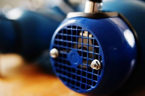
| Drive motor | Provides rotation | Power and speed |
| Gear reducer | Controls rotational speed | Required feeder speed |
| Seals | Limit leakage around shaft | Material and temperature |
| Inlet | Receives bulk material | Hopper connection |
| Outlet | Releases material | Downstream equipment |
Recent Updates
Greater Attention to Dust Safety
Industrial facilities handling combustible powders increasingly pay attention to dust accumulation, ignition sources, explosion protection, and equipment isolation.
Rotary valves can have specialized roles in dust-handling systems, but their suitability for explosion isolation depends on the specific design, material, pressure conditions, detection system, and applicable requirements.
NFPA material describing rotary valves for deflagration isolation emphasizes design characteristics and automatic stopping arrangements when an explosion is detected.
Updated Dust-Atmosphere Classification
IEC 60079-10-2:2026 addresses classification of areas containing explosive dust atmospheres and combustible dust layers. The standard helps establish how areas with combustible dust hazards can be classified for appropriate equipment selection and ignition-risk assessment.
This development is relevant to rotary airlock installations in facilities where combustible dust may be present.
Explosion-Protected Mechanical Equipment
ISO 80079-36:2016 covers non-electrical equipment intended for explosive atmospheres, including equipment that may have potential ignition sources. The standard remains current while a revision is being developed.
For a rotary airlock feeder, this type of framework can become relevant when mechanical components operate in hazardous dust environments.
Improved Material Handling
Modern rotary feeders are increasingly designed around specific material characteristics rather than using one configuration for every application.
Engineering considerations can include abrasive particles, high temperatures, fragile granules, sticky powders, fine dust, hygienic processing, and pressure differences.
Better Monitoring
Industrial plants can connect feeders with sensors and control systems that monitor rotor speed, motor conditions, bearing temperature, vibration, pressure, or material flow.
Such monitoring can help operators identify abnormal operating conditions and schedule inspections based on equipment data.
Integration With Automated Plants
Rotary airlock feeders can be integrated with programmable control systems, variable-speed drives, level sensors, pressure sensors, and upstream or downstream equipment.
This allows material movement to be coordinated with the wider production sequence.
Laws or Policies
International Standards
Rotary airlock feeders can fall under several technical and safety frameworks depending on their application and location. There is no single worldwide regulation covering every rotary airlock installation.
ISO's classification for continuous mechanical handling equipment includes historical standards related to rotary vane feeders and pneumatic handling, although several of those older rotary-feeder standards have been withdrawn.
Therefore, current national regulations, machinery requirements, electrical rules, dust-hazard requirements, and application-specific standards should be checked for each installation.
Combustible Dust Requirements
Facilities handling combustible powders may need to assess whether dust clouds or layers can create an explosion hazard. ISO/IEC 80079-20-2 provides test methods for identifying characteristics of combustible dusts and dust layers for area classification and equipment selection.
Rotary airlocks used for dust isolation may also be evaluated against relevant fire and explosion protection requirements. NFPA 69 contains provisions concerning rotary valves used for deflagration isolation.
Machinery and Electrical Requirements
The motor, drive, control equipment, electrical enclosure, grounding arrangement, and other components must comply with requirements applicable to the installation.
For hazardous areas, equipment selection can depend on the classified area, dust characteristics, temperature conditions, and ignition-protection method.
Regional Compliance
Requirements differ between regions such as the European Union, North America, Asia-Pacific, and other industrial markets. European installations may involve ATEX-related requirements, while North American facilities may apply OSHA and NFPA frameworks alongside applicable electrical codes.
Manufacturers and plant engineers therefore need to evaluate the complete installation rather than treating the feeder as an isolated mechanical component.
Tools and Resources
Feeder Sizing Calculations
Engineering calculations can estimate required capacity from factors such as rotor diameter, pocket volume, rotational speed, filling efficiency, and bulk density.
A simple calculation can provide an initial estimate, but actual performance can differ because powders may bridge, compact, aerate, or flow irregularly.
Material Testing
Material testing can examine characteristics such as particle size, bulk density, moisture, abrasiveness, flow behavior, temperature, and dust explosibility.
These properties influence rotor design, sealing, clearances, material selection, and operating speed.
Variable-Speed Drives
Variable-frequency drives can adjust rotor speed to match process requirements. This can help coordinate feeder operation with upstream storage and downstream conveying equipment.
Pressure Measurement
Pressure sensors can monitor the pressure difference across the feeder or connected equipment. Changes in pressure may indicate process disturbances, leakage, blockage, or other operating conditions.
Condition Monitoring
Vibration sensors, temperature sensors, motor-current monitoring, and inspection records can help track the condition of bearings, drives, and rotating components.
Standards Databases
The Bureau of Indian Standards provides a searchable “Know Your Standard” platform for locating Indian Standards by number or keyword. Similar standards databases are maintained by organizations in other regions.
For international projects, engineers may also consult ISO, IEC, NFPA, OSHA, and applicable regional regulatory authorities.
FAQs
What are Rotary Airlock Feeders?
Rotary Airlock Feeders are rotating mechanical devices that transfer dry bulk materials while helping limit air movement between connected process areas.
How do Rotary Airlock Feeders work?
A rotor containing several pockets rotates inside a housing. Material enters the pockets through the inlet, moves around with the rotor, and falls through the outlet while the rotor helps restrict air leakage.
Where are Rotary Airlock Feeders used?
Rotary Airlock Feeders are used in pneumatic conveying, dust collection, cement, food processing, grain handling, chemicals, plastics, mining, biomass, pharmaceuticals, and other bulk-material applications.
What are the main components of a Rotary Airlock Feeder?
The major components include the rotor, vanes, housing, shaft, bearings, seals, motor, speed-reduction system, inlet, and outlet.
Can Rotary Airlock Feeders be used with combustible dust?
They can be incorporated into systems handling combustible dust, but the application requires appropriate hazard assessment and equipment selection. Explosion isolation depends on the complete system design and applicable standards rather than the presence of a rotary valve alone.
Conclusion
Rotary Airlock Feeders are important components in bulk-material handling systems because they combine controlled material movement with restricted air passage between connected process areas. Their design can vary according to material characteristics, pressure conditions, temperature, capacity, hygiene requirements, and dust hazards. Recent developments place greater attention on dust safety, hazardous-area classification, monitoring, automation, and application-specific engineering. Understanding the rotor, housing, drive, sealing system, and operating conditions provides a useful foundation for evaluating rotary airlock technology across industrial applications worldwide.